Case preparation
We strongly recommend using some tape (masking tape is fine, kapton tape is very nice) on the inside of the case top to reduce the risk of shorting anything out if screws loosen and boards move around later.
It’s also a very good idea to put some masking tape over much of the case halves during assembly to protect them from scratching. The case used for most of the photos in this instructional build was the final pre-production prototype and had not been bead-blasted, so we didn’t worry about the finish.
Wearing some disposable gloves when handling the case is a good idea as well; fingers get amazingly mucky when assembling computer components and oily dirt will tend to stick.
Button wiring & connecting
The APEM type buttons can be mounted into the case top from below since they have a threaded barrel and nuts for both sides of the case. Other buttons may have a solid top that requires installing them from the top of the case. In either case you should connect your switches to the fly leads and test for continuity before going any further. The fly lead connectors will easily fit through the case top holes if you need to fit your buttons from the top.
It’s worth test fitting one of your buttons to check that there is sufficient depth for it to fit correctly; some buttons are surprisingly long. You can also check buttons and their wiring against the printed cross section template we provide. Unusually long buttons may require that you solder the connections cross-wise instead of the more obvious “sticking out” manner. Do *not* forget to insulate the connections. Shorting out the button wiring may damage your Pi.
Switchboard connection preparation
We have noticed that the SenseHAT connections can be very fussy. There is not a great deal of overlap between the header pins and the connector, which occasionally results in no electrical signal. The best answer to this is to gently bend the switchboard header pins out a little. Be very careful with this! It will make installing the SenseHAT a little more fiddly but that is preferable to having to dismantle the case and bend the pins later.
Install the camera
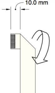
The camera cable needs to be folded according to the following instructions –
Place the cable with the writing side up and the connectors to the left.
![]()
Measure 10mm to the right and fold down
Measure 33mm down from the top corner and fold upwards and to the right
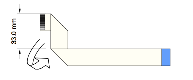
Finally measure 40mm from the bottom corner and fold up
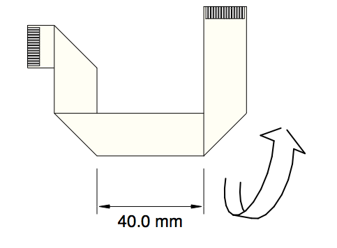
Your cable should fit neatly on top of the printed template provided in the manual.
Connect the camera end of cable to the camera module – remember that the tinned side of the connector goes towards the camera circuit board and that the 10mm long leg is the one to insert into the camera.
If this is a brand new camera module do not forget to remove the protective tape cover! You would have to dismantle almost the entire case assembly to get to it later.
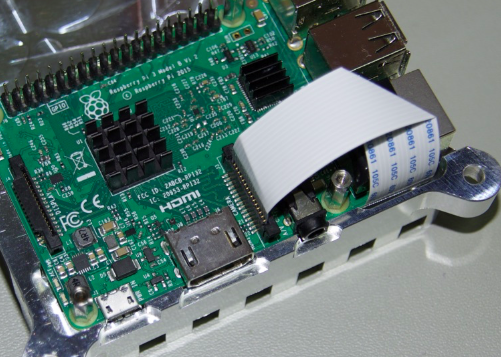
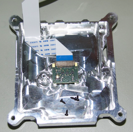 Install camera module in the case bottom with the 4 small self-tapping screws. Use *gentle* pressure to push and twist them because such small screws are very fragile; the holes in the mounting posts are sized to just barely grab the screw threads and reduce the risk of snapping. As long as at least a couple of screws fit ok the camera will be ok! On some camera modules a capacitor is rather close to a mounting hole and there might be a risk of the screw touching something it shouldn’t; in the above picture that would be the top-left mounting hole. If your module has this capacitor a bit close to the screw, it might be smart to leave that out one out.
Install the Pi
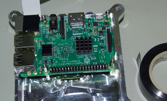
Place the Pi in the case bottom over the mounting blocks, taking care to fold the camera cable around properly; it should stick up next to the ethernet socket. Use the four 11mm long stand-offs to mount the Pi; again, don’t apply too much force to the delicate small screw threads. A tiny drop of oil on each one wouldn’t hurt.
Route the camera cable over the ethernet socket; a strip of electrical tape across the top of the ethernet socket is not a bad idea.
 Connect the Pi end of the camera cable to the CSI connector. Remember to make sure the cable is not trapped between the standoff and the switchboard.
Install the Switchboard, buttons & fly leads
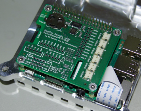
Press the switchboard onto the Pi gpio pins and check that the cable is not getting trapped.
The buttons are arranged as follows, viewed from the top of the case –
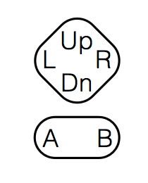
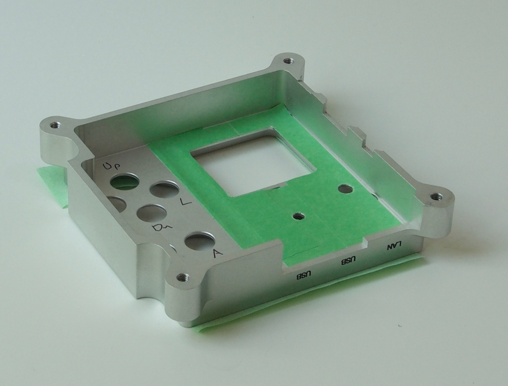
It’s almost certainly a good idea to mark the button locations inside the case top to save time puzzling over the mirrored pattern as you insert the buttons. Of course, if you have buttons that mount from the front you won’t likely have this confusion.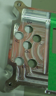
Button locations seen from inside the case, notice how the R/L & A/B are swapped in this view.
The switchboard connectors are labelled with the gpio pin they link to. For each button, plug the fly lead into the socket according to this table.
Label  | Button
GPIO26 |Up
GPIO21 |B
GPIO20 |L
GPIO19 |R
GPIO16 |A
GPIO13 |Dn
The fly lead wiring should be routed as shown to clear the SenseHAT spacer.
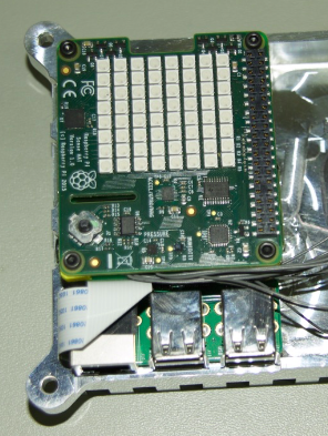
Install the SenseHAT
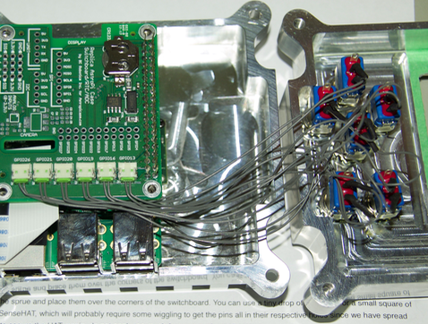
Separate the four small plastic spacers from the sprue and place them over the corners of the switchboard.
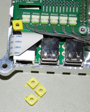
You could use a tiny drop of superglue or a small square of double-sided tape to secure them if you find things sliding around too much. Install the SenseHAT, which will probably require some wiggling to get the pins all in their respective holes since we have spread the pins out a little as mentioned in the Switchboard connection preparation section. Use the four M2.5 screws to secure the HAT; again, do not apply too much force on such small screws.
Onwards to test the functionality